Cross bar
Points to observe before use
The maximum roof load that can be used with additional accessories decreases by the dead weight of the crossbars (13.7 lbs/6.2 kg).
![]() Note that installing the crossbar
increases the vehicle height by 50 mm
compared to the height stated in the
"Technical data" section.
Note that installing the crossbar
increases the vehicle height by 50 mm
compared to the height stated in the
"Technical data" section.
The wrench and the Allen key are located with the vehicle tool kit in the stowage space underneath the trunk floor.
 Replacement parts are available as
Mercedes-Benz accessories. Contact your
authorized Mercedes-Benz Service Center.
Replacement parts are available as
Mercedes-Benz accessories. Contact your
authorized Mercedes-Benz Service Center.
Installing the crossbars
WARNING ![]()
Please follow these installation instructions
carefully. Caution should be exercised to
avoid damage to the vehicle while installing
the crossbars. Also, be careful not to injure
yourself or others while installing and
adjusting the crossbars or loading items on
them.
Each individual step of the installation
instructions, the warning notices, the general
safety precautions and the instructions for
use must be followed exactly. If the crossbars
are not mounted correctly, they and the
objects attached to them could come loose
from your vehicle and cause an accident,
thereby injuring you and other persons and/ or causing damage to property,
including
damage to your vehicle.
WARNING ![]()
Every time the crossbars are mounted, before
you set off on a journey and periodically
during longer journeys, check all the screws on the crossbars to make sure that
they are
secure, and tighten them if necessary. Repeat
these checks at regular intervals as roadsurface
conditions dictate, and at least after
every 1500 miles (2500 km) of continuous
use.
Otherwise, the crossbars, mounted
accessories and the objects attached to them
could come loose from the vehicle causing an
accident, thereby injuring you and other
persons and/or causing damage to property,
including damage to your vehicle.
Do not use lubricant on the screws of the
crossbars. The screws could work loose and
the crossbars could become detached from
your vehicle, together with the objects
attached to them causing an accident,
thereby injuring you and other persons and/
or causing damage to property, including
damage to your vehicle.
WARNING ![]()
Only install the crossbars at the exact
locations designated on the roof rails. The
designated locations for the front crossbars
are between the markings engraved on the
inside of the roof rails. The designated
locations for the rear crossbars are between
the gaps on the roof rails.
Otherwise, the crossbars, mounted
accessories and the objects attached to them
could come loose from the vehicle causing an
accident, thereby injuring you and other
persons and/or causing damage to property,
including damage to your vehicle.
WARNING ![]()
A roof load creates a greater surface area
exposed to the wind and causes the vehicle
to have a higher center of gravity, thereby
changing the vehicle's driving characteristics.
Accordingly, the additional weight on the roof
of the vehicle can have a detrimental effect
on braking, cornering and acceleration.
Never exceed the maximum permissible roof
load or the maximum permissible vehicle weight, even when accessories for the
crossbars (e.g. sk racks, bicycle racks, etc.) are being used. Overloading the
vehicle could
result in an accident. When calculating the
weight placed on the roof please make sure
to add the weight of the crossbars, accessory
racks and the load carried together.
Always adapt your driving style to the road,
traffic and weather conditions, and drive with
added caution when the roof is loaded.
Always drive with extreme care when the
carrier is loaded. Take into consideration that
when the carrier is loaded, the handling
characteristics are different from those when
operating the vehicle without a carrier loaded.
WARNING ![]()
Do not use accessories which have not been
approved by Mercedes-Benz for use in
conjunction with these crossbars. If nonapproved
accessories are used, these
accessories and/or the objects attached to
them could come loose from the vehicle,
thereby injuring you and other persons and/
or causing damage to property, including
damage to your vehicle.
![]() Have a second person assist you when
installing the crossbars. Otherwise, the
vehicle could be damaged.
Have a second person assist you when
installing the crossbars. Otherwise, the
vehicle could be damaged.
![]() Objects that are attached to crossbar
system accessories must not limit or
obstruct the movement of the sliding
sunroof. Otherwise, the tilt/sliding sunroof
could be damaged when it is raised.
Objects that are attached to crossbar
system accessories must not limit or
obstruct the movement of the sliding
sunroof. Otherwise, the tilt/sliding sunroof
could be damaged when it is raised.
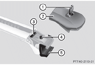
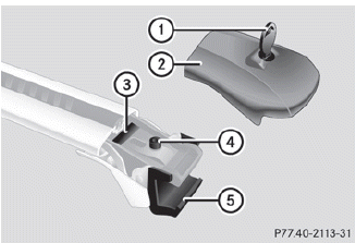
1 Key
2 Cover cap
3 Sticker FRONT (or REAR)
4 Bolt for clamping bracket
5 Clamping bracket
The front and the rear crossbars differ in length. Attention must therefore be paid to the FRONT or REAR stickers 3 on the crossbars.
► Unlock cover cap 2 with key 1.
► Remove cover cap 2 .
Sticker 3 for identifying the installation location FRONT or REAR becomes visible.
► Turn bolt ? counter-clockwise using the Allen key until clamping bracket A is wide open.
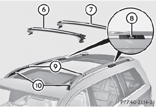
6 Front crossbar
7 Rear crossbar
8 Recesses
9 Markings
10 Roof rails
► Place front crossbar 6 between markings 9 on roof rails 10.
Markings 9 are located on the inside of
each roof rail and are marked with white
lines.
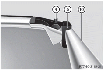
4 Bolt for clamping bracket
5 Clamping bracket
10 Roof rails
► Ensure that clamping bracket 5 is positioned flush with the inside of roof rails 10.
If necessary, adjust the span of the crossbar.
► Tighten bolt 4 slightly on both sides in a clockwise direction.
► Position rear crossbar 7 on roof rails 10 in such a way that the clamping brackets in recesses 8 reach into the roof rails.
► Ensure that clamping bracket 5 is positioned flush with the inside of roof rails 10.
If necessary, adjust the span of the crossbar.
► Tighten bolt 4 a little on both sides in a
clockwise direction.
► Tighten bolts 4 on the front and the rear
crossbar. Maintain a tightening torque of
4 lb-ft (6 Nm) .
WARNING ![]()
Have the tightening torque checked after
mounting the crossbars. The screws could come loose if they are not tightened to
a
torque of 4 lb-ft (6 Nm).
► Attach and lock cover caps 2.
► Store the key and the Allen key back in
the
stowage space underneath the trunk floor.
Adjusting the span of the crossbar
WARNING ![]()
Only install the crossbars at the exact
locations designated on the roof rails. The
designated locations for the front crossbars
are between the markings engraved on the
inside of the roof rails. The designated
locations for the rear crossbars are between
the gaps on the roof rails.
Otherwise, the crossbars, mounted
accessories and the objects attached to them
could come loose from the vehicle causing an
accident, thereby injuring you and other
persons and/or causing damage to property,
including damage to your vehicle.
The span of the crossbar is adjusted to suit your vehicle at the factory. These spans only fit the intended positions on the vehicle.
Only install the crossbars at the marked points and observe the FRONT and REAR stickers 3.
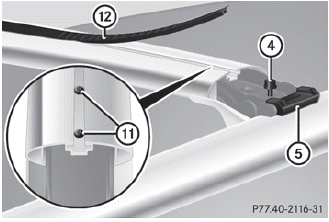
4 Bolt for clamping bracket
5 Clamping bracket
11 Bolts for adjusting the span (a total of 2
on each side)
12 Cover strip
► Pull out cover strip 12 from the
groove until
bolts 11 become visible on both ends of the
crossbar.
► Turn bolts 11 counter-clockwise on both
sides by approx. two turns.
► Place the crossbars on the marked points
on the roof rails.
► Ensure that clamping bracket 5 locks
flush with the roof rails on both sides. If
necessary, pull it out or push it into
clamping brackets 5.
► Tighten bolts 11. Maintain a tightening
torque of 4 lb-ft (6 Nm) .
The width of the clamping bracket is set
correctly.
WARNING ![]()
Have the tightening torque checked after
mounting the crossbars. The screws could
come loose if they are not tightened to a
torque of 4 lb-ft (6 Nm).
► Press cover strip 12 into the groove of
the
crossbar bit by bit.
► Install the crossbars as described.
Removing the crossbars
1 Key
2 Cover cap
3 Sticker FRONT (or REAR)
4 Bolt for clamping bracket
5 Clamping bracket
► Unlock cover cap 2 with key 1.
► Remove cover cap 2.
► Turn the bolts for clamping bracket 5
counter-clockwise until the crossbars can
be removed from the roof rails.
Shortening the cover strip
The cover strips reduce the wind noise that is caused by the crossbars. If additional roof accessories are mounted, it may be necessary to shorten the cover strips.
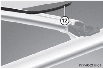
12 Cover strip
► Pull out cover strip 12 from the
groove.
► Mount the roof accessories to the
crossbars.
► Place cover strip 12 flush with the roof
accessories and mark the end of the
crossbar on the cover strip.
► Cut off cover strip 12 at the marked
point.
► Press cover strip 12 into the groove of
the
crossbar bit by bit.
Cover strips are available as Mercedes-
Benz accessories. Contact your authorized
Mercedes-Benz Service Center.
See also:
Approach/departure angle
1 Approach/departure angle, front
2 Approach/departure angle, rear
• Comply with the rules for off-road
driving.
• Do not drive at an angle on slopes,
inclines or gradients, but instead fol ...
Important safety notes
WARNING
For safety reasons, switch off the windshield
wipers and remove the key from the ignition
lock before changing the wiper blades
(vehicles with KEYLESS-GO: make sure that
the on-bo ...
Checklist before driving off-road
– Engine oil level: check the engine oil and
add oil if necessary.
When driving on steep gradients, the oil
level must be sufficiently high to ensure a
correct oil supply in the vehicle.
– DEF ...