Guide lines in the COMAND display
WARNING
Use of rear view camera can be dangerous if
you are color-blind or have impaired color
vision.
Only use rear view camera if you can see and
distinguish all colored guidelines shown by
rear view camera on the COMAND system
display.
WARNING
Please note that objects that do not touch the
ground may appear to be further away than
they actually are, for example:
• the bumper of a vehicle parked behind you
• the trailer drawbar
• the ball coupling of a trailer tow hitch
• the rear end of a truck
• a slanted post
In such cases, you should not use the guide
lines to judge the distance. You may misjudge
the distance, which increases the risk of
impacting the objects.
Even if the object you approach is directly on
the ground, do not approach the object any
closer than the red guide line.
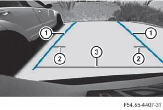
Information in the COMAND display (example)
Guide lines 2 and 3 show the approximate distance to the rear area. Yellow guide line 2 indicates a distance of approximately 3 ft (1 m) and red guide line 3 indicates a distance of approximately 10 in (0.25 m). The distances only apply to objects that are at ground level. Blue guide lines 1 depict the width required for the vehicle. They are used to align the vehicle with the edge of the road, e.g. the curb.
See also:
Automatic comfort-install feature
The front seat belts have an automatic
comfort-install feature. In vehicles with a rear
bench seat with electrically adjustable outer
seats, the seat belts for the outer seats have
an automati ...
Fuse box in the trunk
•► Open the trunk lid
•► To open: release cover 1 at the top right
and left-hand sides with a flat object.
•► Open cover 1 downwards in the direction
of the arrow. ...
Important safety notes
DISTRONIC PLUS regulates the speed and
automatically helps you maintain the
distance to the vehicle detected in front. It
brakes automatically in order to avoid
exceeding the set speed.
On lo ...